The following comprises instructions for the Sorter plug-in.
Contents
1. Introduction to the plug-in
1.3 Position in the overall software package
1. Introduction to the plug-in
When recording the technical data or in the design of container sorter systems, e.g. for planning tasks or simulation studies, it is often very helpful to be able to quickly and easily determine static calculations
of typical performance characteristics using the specified technical data. The Sorter plug-in provides a variety of static calculations and a graphical representation.
Sorter is integrated as a plug-in into SimAssist.
According to the modular basic concept, the full functionality of the SimAssist main menu is available and, for example, several instances of the plug-in can be created or the project can be saved and reopened at a later time.
There is also a link to the PowerPoint and the reporting interface for documentation.
1.3 Position in the overall software package
The Sorter plug-in is part of the 2calculate module, which also contains the plug-ins Monorail, Transfer Car and Cranes. Sorter is therefore available to you if you have licensed the 2calculate module for SimAssist.
The plug-in Sorter provides a shortcut to the PowerPoint and Reporting plug-ins. Thus, the results of the computation can be transferred from the sorter plug-in to a presentation or report.
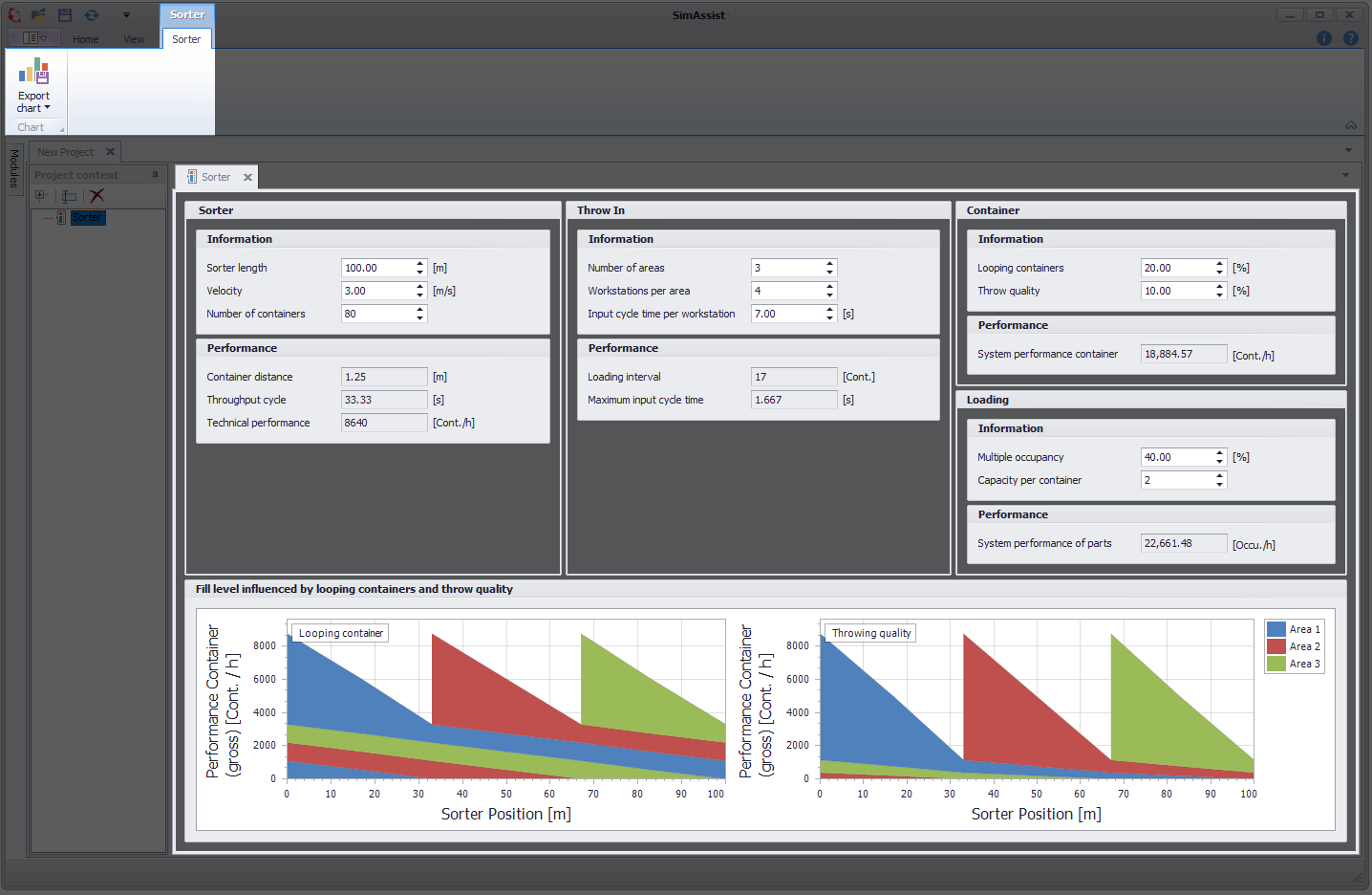
Figure 1 - Interface Sorter
The structure of the plug-in Sorter is divided into 2 sections (see Figure 1). In the upper area is the menu with the possibility to export the diagram.
Below is the key figure area, which is divided into five sections, which are explained below.
•3.1 Sorter
•3.2 Throw In
•3.3 Container
•3.4 Loading
•3.5 Filllevel chart
The following sections describe the individual areas of the Sorter plug-in.
Information
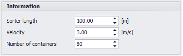
Figure 2 - Information Sorter
Name |
Description |
min. Value |
Sorter Length |
The length of the sorter |
> 0 m |
Velocity |
The speed that the sorter reaches during the operating time |
> 0 m/s |
Number of Containers |
The number of containers located along the route of the sorter |
> 0 |
Performance
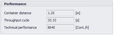
Figure 3 - Performance Sorter
Name |
Description |
Container Distance |
The length between the bow of the first container and the bow of the second container. |
Throughput Cycle |
Describes the time required by a container to circulate the sorter once. |
Technical Performance |
Contains the number of containers that pass in an hour at a certain point. |
Information
Figure 4 - Information Throw in
Name |
Description |
min. Value |
Number of Areas |
The insertion areas, which fill the sorter at equal intervals |
> 0 |
Workstations per Area |
The number of workstations per insertion area |
> 0 |
Inputcycletime per Workstation |
The period after filling a container until filling the next tray, which is needed in a workstation |
> 0s |
Performance

Figure 5 - Performance Throw ins
Name |
Description |
Loading interval |
Specifies the interval of filling the containers with regard to the given Inputcycle and the technical data of the sorter (speed / length) |
Maximum Inputcycletime |
Specifies the fastest possible throw-in cycle for each workstation with regard to the technical data of the sorter (speed / length) |
Information
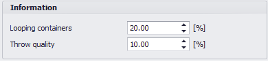
Figure 6 - Information Container
Name |
Description |
min. Value |
Looping Containers |
Looping Containers are filled containers that have not been discarded in the associated ejection area and orbit the sorter once, to the original discharge area where they are then discarded. |
0% |
Throwquality |
Throwquality are filled containers which are not discarded in the associated ejection area, but are distributed to the following ejection areas |
0% |
Performance Container

Figure 7 - Performance Container
Name |
Description |
System Performance Container |
Specifies the number of containers filled per hour. If the Sorter has more than one insertion area, Looping Container and Throwquality (see Figure 4) do affect the performance. |
Information

Figure 8 - Information Occupancy
Name |
Description |
min. Value |
Multiple Occupancy |
The percentage of the containers, which is affected by multi-user occupancy. |
0% |
Capacity per Container |
The capacity per container corresponds to the maximum fill level of a container |
> 0 |
Performance Loading

Figure 9 - Performance Occupancy
Name |
Description |
System Performance of Parts |
The number of parts per hour, that can be filled into the containers. calculated based on System Performance Container (see figure 8) and taking into account Multiple Occupancy and Capacity per Container |
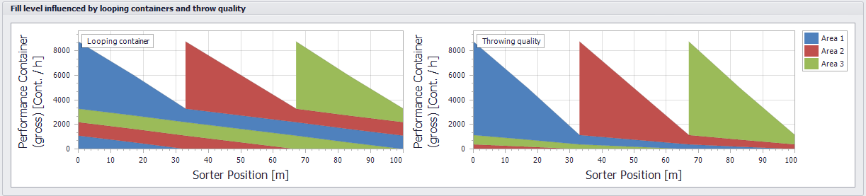
Figure 10 - Graphical Representation of Filllevel
© SimPlan AG - Hanau District Court, Commercial Register (Part B) 6845 - info@simplan.de - www.simplan.de/en